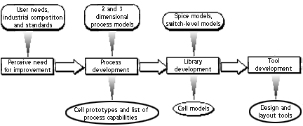
Figure A.1.1
Process, Library, and Tool Development Flow
Modeling--the set of techniques used to predict aspects of an ASIC's behavior under various electrical and environmental conditions--is central to ASIC design and verification. Long before the designer sees the packaged ASIC, various forms of modeling have anticipated and shaped all of its important behavioral aspects. Software models, by far the most common, are becoming increasingly complex and accurate. While carrying out modeling tasks, both anticipated and unanticipated translations are often necessary.
Translation changes models and testing schemes from one form to another. ASIC design and test tools support the bulk of translation needs. However, no modeling tool set supports all types of models. A design group's tool set often fails to support essential modeling needs, such as stuck-at-fault analysis. When this problem occurs, the question is: "Can the design team create a model to achieve the desired benefit in an economical way?" The answer lies in the cost and effectiveness of buying or writing translators that move the model from one tool to another. Given the complexity of today's ASIC designs, translation is not an easy task.
Today's profound levels of ASIC complexity require simulation-based methodology (i.e., computer modeling) for timely, economical and reliable ASIC development. Simulation allows designers to develop ASICs entirely on computers. The days of modeling ASICs exclusively with breadboard prototypes are rapidly coming to a close as the amount of information necessary to accurately model ASICs becomes manageable only by computer. Today, computer modeling has become so competitive and central to design that most vendors guarantee the predictions of their simulators about the final part's behavior.
The philosophy that drives modeling in an ASIC program can be simply stated as "model early, often, as accurately and completely as possible, in an economically intelligent fashion." This philosophy holds for everyone involved in the ASIC business: ASIC vendors, ASIC designers, and third party organizations. The same philosophy holds on all levels of ASIC modeling, from the top level (specifying objectives and requirements) to the bottom level (simulating transistor behavior).
This appendix has two goals: to inform the reader about how modeling and translation fit in to ASIC technology, and to provide insight into how these issues effect making economical decisions.
To accomplish these goals, we begin with a section on "Model Development," reviewing the far-reaching world of modeling and model creation at all levels including fabrication processes, cell libraries, and modeling tools. We then relate this information to vendor evaluation issues.
Section 2: "Modeling and the Design Cycle," describes the tools available to the designer for ASIC design and verification, and discusses how to be a smart consumer of these products.
Section 3 is devoted to "Translation," describing its possibilities and limitations to show how it can save time and money, as well as how it can become a major bottleneck to the progress of an ASIC program. We then give some tips on how to exploit the former and avoid the latter.
Because of the vibrant EDA market, tool sets usually outpace the processes and libraries they intend to model in terms of handling complexity, performance, and accuracy. The EDA industry may put out products that can simulate an ASIC running at 50 gigahertz, but if processes can only fabricate ASICs that run at 2 gigahertz, the extra simulating power cannot be used effectively. Similarly, if simulators can predict parametric performance parameters with 0.01 percent accuracy, this is immaterial if library parameters have only 0.1 percent accuracy. Thus, the most pervasive limitation to modeling is library development.
When vendors develop fabrication processes, library development naturally must follow the process developments the libraries aim to reflect. Thus, designers cannot use tools to model these processes until the vendors develop their libraries. As cell behavior becomes more complex and multi- dimensional, each behavioral level to be modeled demands larger and more accurate data bases for correct simulation. Finally, library development is a voluminous task: hundreds of cells require modeling, and each cell model must have several versions corresponding to the many tools that designers use to support it.
We now discuss process, library, and tool development in greater detail, referring to figure A.1.1.
Figure A.1.1
Process, Library, and Tool Development Flow
Three factors influence both building new processes and improving preexisting processes (such as scaling devices to smaller dimensions): user needs, industrial competition, and government and industry standards. Users provide feedback to vendors about what process improvements would best serve their future goals. Competition in industry constantly motivates vendors to make their products faster, cheaper, and more reliable. Standards motivate process changes that have been modified, such as updating test method standards in MIL-STD-883, or standards that have been created such as the IEEE JTAG Boundary Scan, IEEE STD 1149.1.
Unlike most higher level models, process models take relative positioning of transistor components into account (i.e., they use distributed parameters) and are able to model the shapes of those components with great accuracy. Developers then fabricate prototypes of parts and single cells for process debugging and for library development. Once a process is finalized, developers generate a list of process capabilities to guide library and tool development.
Vendors use two types of models to develop and verify cell libraries: SPICE (circuit-level) and switch-level models. SPICE models are at a higher level than process modeling and switch-level modeling is at a higher level still.
SPICE models perform steady-state and transient analyses to predict circuit performance. They use more approximate parameters for each logic component than those used during process modeling, and do not consider placement and routing. Therefore, process modeling must consider all electrical side effects due to component proximity before modeling at the SPICE level. Just as process models should verify transistor behavior before using SPICE, SPICE should verify cell behavior before using switch-level models.
Switch-level models consider only whether transistors are "on" or "off." Modeling on this level is considerably faster than SPICE since it does not consider capacitive, resistive, and other electromagnetic effects of transistor performance. This allows entire designs to be modeled, rather than individual cells.
Once developers satisfactorily model these cells at the circuit and switch levels, they feed the results to a model compiler in the form of a functional description, timing data, and physical data. The model compiler then generates cell models formatted for the vendor tool set and often also for other EDA tools.
Some model compilers are more automated than others�the more automated they are the better. Automation reduces the risk of inconsistent models, reduces human error and tedious labor, allows cells to be updated more efficiently as the process and model accuracy improves, and above all, increases accuracy.
Tool development aims to assure that designs are "correct-by-construction." This means that if the tool accepts a given design and models its performance, the process will indeed be able to fabricate that design with its predicted performance. Achieving this goal requires that tools automatically check for adherence to design rules. Design rules such as minimum spacing between wire set standards to assure that designs are consistent with process capabilities. Besides circuit design tools, vendors must develop layout tools.
Layout tools determine and model the geometrical positioning of all components (known as "place and route"). Vendors usually run layout software once the users design logic for their ASICs. Users then apply information learned from place and route to account for interactions between components in their logic models (in steps known as "back- annotation" and "post-layout analysis"). Designers sometimes use an intermediate step, called floor planning, to approximate layout information. This enhances the accuracy of timing delay models and makes routing more efficient.
ASICs are modeled on a variety of levels. From the top level to the bottom level, these are:
Designer Responsibility: |
|
| Vendor Responsibility: (Process and Library Development) |
|
Hardware description languages (HDLs) provide the foundation for a relatively new top-down modeling strategy. HDLs cover multiple levels of modeling, from algorithmic behavior to gate level. HDLs are useful because they maintain a similar syntax throughout these modeling levels. Similar syntax improves translation accuracy between HDL models and HDL modeling levels. Similar syntax also allows simulating designs with components at different modeling levels. The flexible HDLs are just one of the many tools used in design systems.
Today's ASIC design systems include tools for synthesis, optimization, logic simulation, hardware acceleration, timing analysis, automatic test pattern generation, fault grading, and timing-driven layout. These tools allow designers to model as low as the gate level.
Ideally, design systems allow designers to design from the top level (requirements) to the bottom level (gate), assuming that the vendor's libraries have been previously modeled sufficiently at the levels below gate level. As ASIC technology matures, it is rapidly migrating toward this top-down approach.
The flow can be summarized as follows. Beginning with system objectives, the user defines ASIC and system level requirement specifications, using verbal or formal methods. Engineers implement these specifications by designing the ASIC at the gate level, or by translating these specifications to a hardware description language (HDL) which in turn synthesizes (produces) a gate-level model. HDLs can model at the behavioral, register-transfer, and logic levels. Designers then simulate their gate-level models, using all or some of the following automated analyses: functional, parametric, testability, radiation, thermal, mechanical, and manufacturability. These analyses either verify the pre- and post-layout models, or reveal the need to manually modify the model at the gate, hardware description, specification, or system objectives level.
The rest of this section addresses specific aspects of this flow in greater detail.
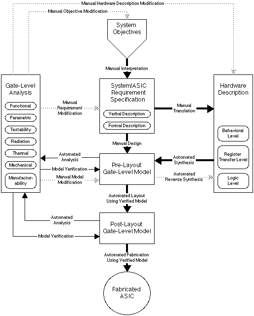
Figure A.1.2
ASIC Program Modeling Flow
In Figure A.1.2, three types of arrows connect modeling levels:
The mathematical basis of formal methods gives them a compelling advantage over simulation. The mathematical models cover entire ranges of possible inputs to a system, and can be used to prove that assertions are true throughout these symbolically represented domains. Simulation, on the other hand, cannot prove anything in general, since it is empirical rather than theoretical. This means it relies on specific test cases for analysis. Simulation can reveal inconsistencies on a case-by-case basis, but without an infinite number of these test cases, it cannot prove that there is not some untested case that would cause a failure. Formal methods not only have the power to detect the presence of inconsistencies, as in simulation, but also the absence of inconsistencies, through symbolically generalized formal proofs.
Although powerful, formal methods are extremely labor intensive and thus rarely used. Simulation often suffices for practically thorough verification. Today, formal methods for integrated circuits find utility only at the requirement, behavioral, and register-transfer levels. Even at these levels, they are extraordinarily time consuming. For lower level modeling, designers must translate formal specifications to other tools. Engineers must use formal methods carefully, since they have no benefit if engineers do not fully understand the system that the formal methods attempt to describe.
Formal methods help only to the extent that designers know what needs to be proven to make a system reliable. Thus, formal methods can prove that an already well-engineered system conforms with its objectives, but they cannot create consistency. In short, there is no such thing as formal development; only formal verification.
Also formal methods are useless if they implement less rigorously verified specifications. Proving that implementations agree with specifications only helps to the degree that the specifications represent top-level objectives, or that the specifications prove consistent with top level objectives.
In principle, formal methods can be applied at any modeling level, to prove that an implementation agrees with its specification. However, tools still need extensive development to make this a reality. As formal methods become more accessible, wise verification strategies will often involve a mix of formal methods and simulation.
Synthesis is a powerful tool for translating a design from the HDL level to the gate level. Before HDLs became prevalent, requirement specifications were manually translated directly to the gate level. Automating gate-level implementations by using synthesis saves designers time and reduces human error. HDLs support three levels of ASIC modeling: behavioral, register-transfer, and logic. However, at present most synthesizers can only implement register-transfer level models to produce a gate level representation.
All HDL model levels (behavioral, register-transfer, and logic) describe ASICs in a Pascal-like procedural fashion. Behavioral models describe ASICs in terms of high-level functions, without considering registers or combinational logic. Register-transfer models describe ASICs at a lower level, by modeling them as a set of registers that change contents, ignoring the logic that induces the changes. Logic models describe ASICs at the lowest HDL-supported level, the gate level. Modeling an ASIC often uses an HDL description that mixes these strategies.
Not all HDL descriptions, even at the register-transfer level, synthesize into working gate-level designs. Usually, problems occur when accounting for timing. For instance, VHDL allows spikes to be dealt with differently for each port, whereas many other HDLs do not have such flexibility (spikes occur when an input changes before the result of the previous input propagates to the output).
Designers can also translate gate-level models to HDLs. This practice, called reverse synthesis, allows designers to either use HDL versions of old gate-level designs that were not first designed using an HDL, or incorporate them into new designs on an HDL platform.
The trend toward design language standards reduces translation problems. However, standards still remain far from universal. VHDL, EDIF, and SDF are today's design language standards that simplify translation, but until one standard prevails, translation between standard and non-standard formats remains a monumental task.
Creating "universal" design language standards today poses a dilemma. Since the ASIC industry uses many platforms, languages, and formats, standards must support many design styles to achieve wide-spread support. This makes design language standards undesirably complex. Furthermore, this often drives developers of systems that use the standards to define subsets of the standards. Consequently, these subsets become incompatible with each other and in effect unmake the standard. Once developers deviate from a standard, then it is no longer a standard.
Users anticipate and minimize translation problems by understanding the limitations of a vendor's tool set during vendor evaluation (see Section 2). QML and QPL specify that the vendor supplies all necessary design tools to the user, and handles placement and routing in house. However, the vendor may not adequately support one or more modeling areas, particularly in high- reliability applications. The user must weigh all issues regarding these deficiencies: availability or ease of writing translators to third party tools that fill the modeling need, and the efficiency and reliability of performing such translations.
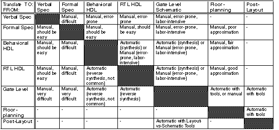
Table A.1.1 shows a matrix illustrating several modeling levels. This matrix also shows if and how engineers can accomplish translations. The table represents successively lower levels of modeling along both the rows and the columns. Each cell in the matrix represents translating from the row modeling level to the column modeling level. Cells with dashes mean engineers rarely, if ever, perform translations. All other cells indicate whether translation is manual (no tool exists today to automate the process) or automatic. If the translation is automatic, the table indicates the type of tool needed. The table also offers other comments concerning possible problems, where appropriate.
There are many tools that can translate to and from ASIC and system levels:
Formal methods are in their infancy for use in ASIC design. However, as EDA systems become more powerful and formal method tools become more efficient, then formal methods can greatly strengthen the link between top-level requirements, specifications, and final ASIC parts.
In recent years EDA vendors have recognized that no one system can have every feature that users require. The solution that has emerged is known as "open framework" tool design. This approach allows designers to link tools more easily than in the past. Tool vendors enable linking by making public the nature of their data formats and tool interface designs. Vendors are also making additional tools just for creating links. Hybrid systems, customized to a particular users' requirements, result from this activity.
Modeling styles and tools changes almost as fast as microelectronic device designs. They can only increase in their importance to ASIC work as they continue to improve their accuracy and their ability to model new aspects of microelectronic technology.
Now you may jump to: